What Are the Top Types of Control Valves?
Choosing a control valve is not simply a matter of selecting the largest or most familiar design. The right valve must match the fluid, pressure range, temperature, flow behavior, and required control accuracy. A poor choice can create noise, vibration, cavitation, unstable flow, or unnecessary maintenance. This article, “What Are the Top Types of Control Valves?”, examines the main valve designs used across processing, water treatment, power generation, and industrial automation.
Bela G. Lipták, a respected process-control authority, described the control valve as “the final control element in a process control loop.” That role makes valve selection especially important. At Control Valves, engineers often compare globe, butterfly, ball, diaphragm, and pinch valves against real operating conditions. Each type has practical strengths. Globe valves offer precise throttling. Butterfly valves provide compact, economical flow control. Ball valves can deliver strong shutoff and efficient flow paths.
The details matter.
A valve that performs well on clean water may struggle with abrasive slurry. A compact design may also sacrifice rangeability or repair access. These trade-offs are easy to overlook when specifications appear complete. In practice, reliable selection requires more than catalog comparisons. It requires checking installation space, actuator response, materials, maintenance history, and failure behavior. No single valve type is best for every process. That is the part many simplified guides miss. The following sections compare leading control valve types, explain where each design works best, and identify limitations that deserve closer engineering review.
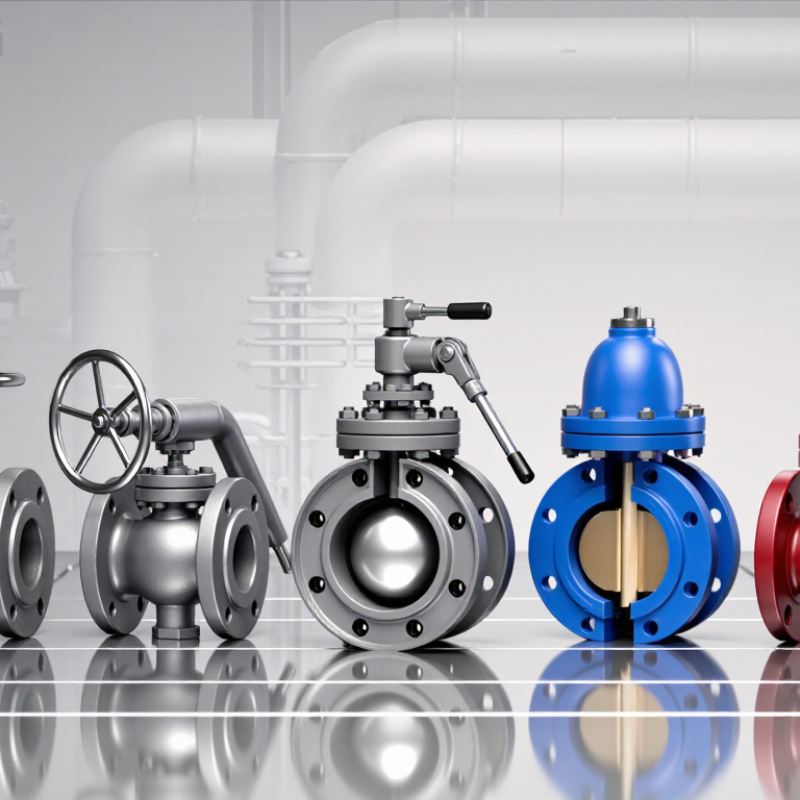
Globe Valves: Precise Throttling Under IEC 60534-2-1 Sizing Rules
Globe Valves: Precise Throttling Under IEC 60534-2-1 Sizing Rules
Globe valves remain a strong choice when flow control must be accurate and repeatable. Their guided plug moves toward a seat, creating a predictable restriction. In practical commissioning work, this design helps operators adjust flow without sudden changes. It also supports stable pressure control in steam, water, and process lines.
IEC 60534-2-1 provides a structured method for sizing these valves. Engineers evaluate the required flow coefficient, pressure drop, fluid density, temperature, and valve travel. The calculation must also consider choked flow and cavitation risk. A valve that appears correctly sized may still perform poorly if pressure recovery is overlooked. That mistake happens more often than it should. I have seen oversized globe valves hunt near the seat, causing noisy operation and unnecessary wear.
Tips: Start with verified process data. Use the highest, normal, and lowest flow cases. Check whether the selected valve operates within a practical travel range, not just its maximum capacity. Confirm actuator force and fail position separately. When uncertainty remains, document the assumption and review it with the process team. Small gaps in data can change the final size.
Ball Valves: 90° Actuation and ANSI/FCI 70-2 Leakage Classes
Among control valve designs, ball valves stand out for their quarter-turn, or 90-degree, actuation. A pneumatic or electric actuator rotates the stem from open to closed. That short movement reduces operating time and simplifies emergency isolation. In modulating service, the ball and seat must match the flow requirement. A full-port ball valve may limit pressure loss, while a characterized opening improves control at low flow. The detail is easy to miss.
ANSI/FCI 70-2 leakage classes describe allowable seat leakage during a defined test. They are not general quality grades. Classes II and III permit more leakage than Classes IV, V, and VI. Class V uses a liquid test and tighter limits, often for demanding shutoff. Class VI addresses very low gas leakage with a stated bubble rate. It still does not mean absolute zero leakage.
In practice, selection starts with pressure, temperature, fluid, line size, and actuator torque. A high leakage class can increase seat sensitivity to solids, misalignment, or thermal distortion. Clean installation matters. Inspectors should verify the test medium, differential pressure, seat material, and measured rate. A certificate without test conditions is incomplete evidence. I would question a Class VI specification for dirty service; it may look precise, yet fail early.
Ball Valves: 90° Actuation and ANSI/FCI 70-2 Leakage Classes
Ball valves typically use quarter-turn actuation, rotating approximately 90° from fully open to fully closed. The chart compares the commonly cited maximum seat-leakage rates for ANSI/FCI 70-2 Classes II–IV, expressed as a percentage of rated valve capacity.
Note: ANSI/FCI 70-2 Class I has no specified leakage limit, while Classes V and VI use different test criteria rather than the percentage scale shown here.
Butterfly Valves: High-Capacity Flow Within API 609 Design Standards
Butterfly Valves: High-Capacity Flow Within API 609 Design Standards
Butterfly valves remain a practical choice when pipelines need high flow capacity, compact installation, and fast shutoff. Their disc rotates around a central or offset shaft. This design creates less obstruction than many globe valve arrangements. In large water, cooling, chemical, and process lines, that difference can reduce space and actuator demands. The details matter.
A 2023 MarketsandMarkets report valued the global control valve market at approximately USD 7.9 billion. It projects growth to about USD 10.8 billion by 2028, supported by water treatment, energy, and process automation. These figures do not prove that butterfly valves fit every duty. They show sustained demand for controllable industrial flow. API 609 provides dimensional, pressure, and testing guidance for butterfly valves used in critical piping applications. Engineers still need to verify pressure class, temperature limits, seat material, shaft design, and leakage requirements.
In field assessments, a lug or wafer body can simplify installation between flanges. An offset-disc design may reduce seat wear during repeated cycling. But high capacity is not the same as precise throttling. Poor sizing can produce noise, vibration, or unstable flow. That risk is easy to underestimate. The Valve Manufacturers Association reports that valve performance depends strongly on application selection and maintenance practices. A responsible specification should compare torque data, cavitation risk, isolation needs, and available inspection access. API 609 compliance is valuable, but it is not a substitute for engineering judgment.
Diaphragm and Pinch Valves: Corrosion Resistance for Slurry Service
In slurry service, valve selection depends on more than nominal pressure. Sharp silica, tailings solids, acidic liquor, and fluctuating flow can attack seats and bodies. NACE International’s IMPACT study estimated global corrosion costs at 2.5 trillion dollars annually, equal to 3.4% of global GDP. That figure covers many assets, not valves alone. Still, it shows why material decisions deserve measured engineering, not habit. Diaphragm valves isolate process fluid from the operating mechanism. A reinforced elastomer diaphragm can handle corrosive chemicals and moderate solids without a traditional stem seal. They support throttling and clean shutoff, but abrasive particles may shorten diaphragm life. Temperature and cycling frequency matter.
Pinch valves use a flexible sleeve that closes around the slurry. The sleeve becomes the sacrificial barrier. This geometry tolerates fibrous material, coarse particles, and settling mixtures. Full-bore flow can also reduce blockage risk. The USGS Mineral Commodity Summaries 2025 recorded roughly 22 million metric tons of mined copper in 2024. That production illustrates the enormous solids-handling scale behind modern processing. However, copper output does not directly measure slurry volume. It is only useful context. Operators should inspect sleeve or diaphragm wear, closing response, and pressure-drop changes. I would not specify one valve universally. A pilot test using actual particle size, pH, temperature, and solids concentration can outperform a polished datasheet.
Control Valve Selection: Cv, Rangeability, Pressure Drop, and Actuation
What Are the Top Types of Control Valves?
Control valve selection starts with the process, not the valve catalogue. Globe valves suit precise throttling and high pressure drops. Butterfly valves offer compact control for large pipelines. Ball valves provide tight shutoff, although their control behavior can become less stable at low openings. Diaphragm valves help isolate corrosive or contaminated fluids. Each type has limits.
Cv indicates how much flow a valve passes under defined pressure conditions. A valve that is too small may create excessive velocity, noise, and erosion. An oversized valve may operate near its seat, where small stem movements cause large flow changes. That is poor control. Rangeability matters here. It describes the useful flow span between minimum and maximum controllable rates, not merely the mechanical travel.
Pressure drop deserves careful review. Some systems need a deliberate pressure loss for stable regulation, while others cannot tolerate it because of pumping costs or flashing risk. Actuation must match the process response. Pneumatic actuators are commonly selected for fast, modulating service, while electric actuators can simplify installation where compressed air is unavailable. Fail-open, fail-closed, or fail-in-place action should reflect the safest process condition.
Field checks often reveal assumptions that sizing sheets miss. Actual fluid temperature, changing viscosity, and intermittent demand can alter performance. I have seen a technically correct Cv calculation fail because the normal operating point was ignored. A second review is worthwhile.